Avionics sub-panel | 1.27.2021 - 1.28.2021
I started the evening with a long conversation with a friend (who has more electrical engineering experience than I do) about the modifications that I'm thinking of making to Wayne Lanza's "Gold Box" gear control system to better integrate with the G3X and streamline the panel install. More to come on that, but I've decided on a path forward.
After that, I went to the garage and started fabricating the avionics sub-panel. This panel sits behind the main panel and acts as a place to put things that aren't mounted to the panel itself. Remote mount radios, electrical stuff, etc.
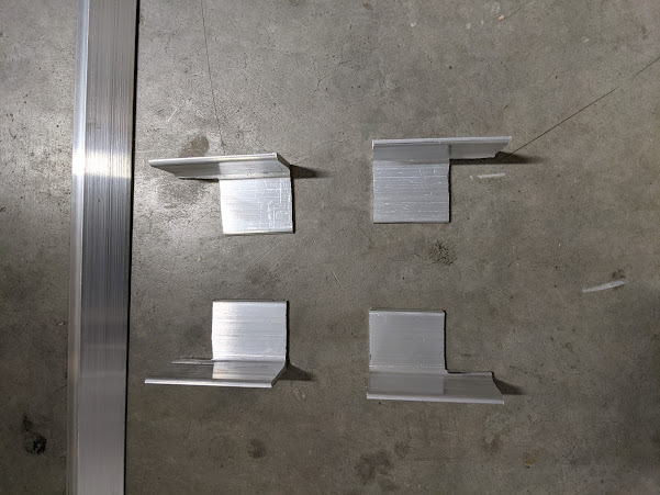
The first step was to fabricate the brackets. I did this with 1.5" angle aluminum by cutting them to short, ~3" lengths, and then notching out an area on them for the crossmembers to sit in. I did this (rather than just making smaller brackets) so that the brackets would have more surface area to adhere to the fuselage when they're bonded in.
 |
| Cut fuselage mounting brackets |
After that, I made a rough measurement and cut the crossmembers out of 1" angle aluminum. You'll need two pieces of 3 ft length to start with, only a little is cut off.
 |
| Fit of crossmember and bracket |
Once that's done, you can start leveling and figuring out where everything will end up in the fuselage behind the panel. I started by finding a rough spot where I wanted the pilot side bracket closest to the cabin, then leveling the crossmember and finding the spot for the copilot's side bracket. Once that was marked, I found the spot for the rear brackets based on the front brackets, temporarily clecoed everything, and checked for level. Came out perfect!
Once that was done, I prepped the fuselage surface and prepared some structural adhesive with cabo and adhered the brackets in place. I then left them to cure overnight. (Side note, I've been heating the garage to ~72 or so with an electric heater for the various layups and adhering. I *really* need to get a kerosene heater or something to help with the electric bill, but this is holding a good temperature and the plane really shouldn't be in the garage much longer.)
 |
| Brackets adhered in place and riveted. |
 |
| Here's how it looks with the crossmember. |
The next day, I fabricated the rest of the sub-panel out of the crossmembers and some 1/16" 6061 sheet. The crossmembers were riveted to the sheet, but I made sure that the whole thing would be removable while riveted first. Depending on fit, this may not be possible for all, so check before you start riveting.
 |
| Ta-da |
One mistake I made here was that I realized about halfway through riveting that I should have used countersunk rivets so that things could easily sit on top of them if it's needed later. You'll note that the rivets in the rear are countersunk. I don't think this will be a big deal for what I have planned, and if it is, I'll just drill them out and replace.
Also, our exhaust came in from Velocity! We decided to go with four individual straight pipes out the bottom of the fuselage for simplicity, weight, and cost. More on this later, but we discovered that cylinder #1 exhaust interferes with it's own intake tube. The two rearmost intake tubes (cyls #1+2) already interfered with the cowling and I had planned to bump it out to make room, but I have different plans now. Stay tuned for more on that.
That's it for today!
- Jeff

Comments
Post a Comment