Posts

Showing posts from January, 2021

Heater flapper install, intake tube mods | 1.31.2021

Image
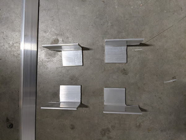
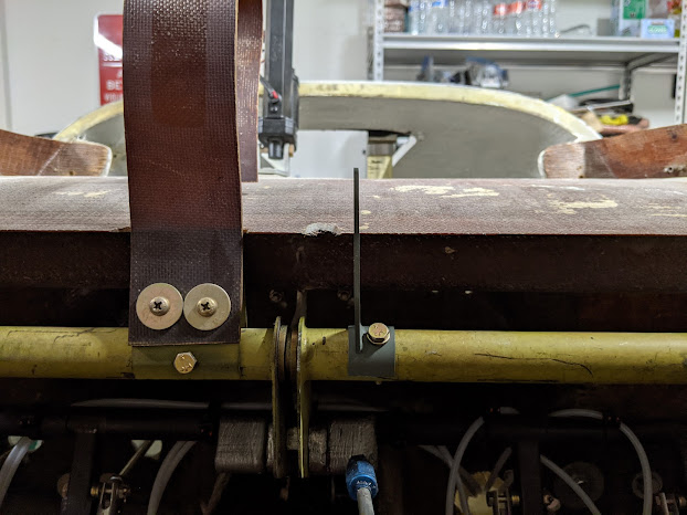
Finally got around to installing the heater flapper control. Basically needed to mount the control, route it through the canard bulkhead, and connect. Started by fabricating the hardpoints and figuring out the mounting location. The best mounting location I could come up with was on the pilot's left hand side on the fuselage. Since the control would need to be canted out, I made the front mounting point out of 1" (if I'm remembering right?) square aluminum. I then installed a nutplate in this. The control was then installed to the hardpoints with adel clamps, and the hardpoints were structurally adhered to the fuselage and secured to the fuselage to cure with rivets. Ready to adhere. Installed location. I then routed the cable through an existing hole in the bulkhead. Not the most optimal location, but I wanted to use an existing hole rather than make another. The cable was trimmed to length, and the rest of the hardware was installed per plans. Works great!   I then start

SDS CPI-2 Arrival | 1.29.2021

Image
Our SDS CPI-2 arrived today! We had debated installing an electronic ignition now vs. keeping the magneto that was installed and installing the EI later, but I realized that I'd much rather do the work now than have to retrofit. We may add a second one later, but for now, we're only replacing the left (starting) magneto. Gets 95% of the benefits, plus I have diverse redundancy with the mag. Unboxed and inventoried everything. First impressions: these parts are gorgeous. Fit and finish is 10/10. Just look at that beautiful anodized billet aluminum. I'm a sucker for well machined parts.   Started to install it. Removed the left mag. Removed the left mag adapter/extension. Removed the studs and ordered the standard length ones. Mag removed with extra long studs showing.   Also removed the prop extension and stater ring gear (again...). Started to mount the crank sensor, but realized that I have the wrong starter ring gear. The starter ring gears come in two alternator pulley c

Avionics sub-panel | 1.27.2021 - 1.28.2021

Image
I started the evening with a long conversation with a friend (who has more electrical engineering experience than I do) about the modifications that I'm thinking of making to Wayne Lanza's "Gold Box" gear control system to better integrate with the G3X and streamline the panel install. More to come on that, but I've decided on a path forward. After that, I went to the garage and started fabricating the avionics sub-panel. This panel sits behind the main panel and acts as a place to put things that aren't mounted to the panel itself. Remote mount radios, electrical stuff, etc. The first step was to fabricate the brackets. I did this with 1.5" angle aluminum by cutting them to short, ~3" lengths, and then notching out an area on them for the crossmembers to sit in. I did this (rather than just making smaller brackets) so that the brackets would have more surface area to adhere to the fuselage when they're bonded in. Cut fuselage mounting brackets A

Cutting the panel | 1.23.2021 - 1.24.2021

Image
My weekend project was to get the panel to the 99% mark for installation of avionics. Largely, I succeeded. There's only two more holes to drill, both of which I don't know the diameter of, because they're the only two switches that I don't have on hand. On Saturday, I worked on locating and drilling the hole for the avionics stack and installing the front avionics rails. Our avionics stack currently consists of a GMC 507 autopilot control, GMA 245 audio panel, and GPS 175 navigator. Eventually, there will probably be a traditional second nav/com below these (GNC 255), but for now we're slumming it with a single radio and only GPS navigation. The radio will likely be installed within the next year, but we're holding off for now. This hole was pretty simple to locate and cut. Every cut on this panel started undersized, because I only get one real shot at this, so I'd rather cut more out later than cut too much to begin with. I'd then either trim more off,

Throttle and mixture cable installation | 1.22.2021

Image
Since the engine control panel is now mounted, it's finally time to install the throttle and mixture cables back to the engine! Started out by applying the carbon fiber 3M wrap film that we *were* planning on using on the entire panel. I've decided that it's a bit too shiny/busy for the entire panel, but think it will look good as an accent on the engine control portion of the panel. Likely the rest of the panel will be flat or satin black or gray, but the samples have yet to arrive. Wrap film before trimming. Once that was done, I drilled through the pilot holes for the throttle and mixture (leaving the invisible pilot hole for the prop control) and pulled them through the panel, down into the conduit, and out the back of the plane. Once everything was out the back of the plane, I started working on mounting the brackets and drilling for the cable clamps. The cables were first pushed all the way forward (full throttle and mixture), *almost* touching the stops in the cabin

Throttle panel, induction air flange, oil door hartwell latch, door strake extensions | 1.21.2021

Image
The throttle panel flange had cured, so got to work on cleaning that up. Also cut the oil access door for the Hartwell style flush latch. Here's the throttle panel as laid up. Somehow I don't have a picture of it after I trimmed it. Once that was trimmed, I measured and drilled pilot holes for the engine controls to use to hold to the layup/mounting point that exists in the fuselage. I then drilled holes through the panel and flange that will get drilled out later for nutplates, but for now serve as holding points for the clecos to temporarily hold it together. The three clelos on the engine control panel are where the holes for the throttle, prop (if I had one), and mixture will go. Installed Once that was ready, I made up some structural adhesive with cabo and adhered it to the existing mounting point. If the mount point had not already existed, I would have just done a layup here from the fuselage onto the panel. (Editor's note: I originally intended to later do a layup

Pitch servo positioning and hardpoints | 1.20.2021

Image
Also in the shipment from Velocity the other day was our autopilot elevator arm, so I began work on positioning and installing the autopilot pitch servo. This install was a bit tricky, because with the relatively small throw of the Garmin (and other newer) servo arm, the geometry gets a bit odd. Basically, this needed to be positioned pretty far back on the canard to get the full throw without hitting the Garmin overcenter protection bracket. I also had to carve out some of the trailing edge of the canard to make room for the linkage, with how low on the elevator bracket it had to be mounted to get the full throw. Here's the elevator arm (right) drilled and secured. I put this just outside of the bushing that's inside the torque tube in the middle. Once everything was positioned and I was confident that the geometry would work (1.5 hrs later...), i mixed up some structural adhesive with cabo and adhered the hardpoints in. Duct tape holds everything in place. Also this wasn'

New panel fit/layout, seat foam | 1.18.2021 - 1.19.2020

Image
Our new panel arrived from Velocity! Older kits had been supplied with a "canted" panel, that angled the radio stack towards the pilot. With newer electronic instruments, a more typical panel is completely flat; especially for what we are going to do with it. Here's the new, untouched panel. Rather freshly laid up too; pretty sure they made this to order. Since there are a bunch of tasks hinging on getting this thing fit and the throttle corner cut out, I set to work on fitting this to the plane. This comes pretty oversized, so it needs to be cut down, particularly in height. It would be sweet to keep the height as-is to have more (much needed) panel real-estate, but you'd have terrible forward visibility. Since I liked (and had already verified everything fit within) the way the Stabells had cut the previous panel, I traced the rough outline of that panel onto this one, then cut around it, leaving more material to fine tune things after. After a *bunch* of fine tunin

Flow transducer, overhead panel | 1.17.2021

Image
Figured that since I've been working on sensors lately, now would be a good time to get the fuel flow transducer mounted. In retrospect, I did this and then realized that the hose routing probably won't work because of the cooling plenum, and I'm not sure how I'm going to route it now. It might still work where it is. Maybe bummer? This is the transducer. It measures fuel flow, so that you can calculate fuel burn, monitor usage, etc. I don't have any good pictures, but I fabricated hoses and then wrapped the transducer itself in fireshield. It was then attached to the fuel servo, and the fuel servo was re-installed for good (hopefully). As a side note, there is so much conflicting mounting advice on this little sensor, even from the manufacturer themselves. I spent a ton of time trying to find the best place to mount it and decided on an "outlet up" orientation, on the line that supplies the fuel spider. Flow transducer in orange firesleeve. I then moved o