Posts

Starter connections, fuel servo | 12.10.2020 - 12.11.2020

Image
Started running the first of the wiring. Since the engine's in place, figured it made sense to terminate the starter wire. I used 2 ga wire; some people use 4 ga wire for the starter and I guess it typically works fine, but technically for the amperage drawn by the starter and the distance from the battery a 2 ga wire is better. I briefly considered using 4 ga, but when I bought the kit, it came with a whole bunch of MIL-W-22759/16 wire in varying sizes. I had enough 2 ga to run to the starter, but not enough 4 ga. Since I had the 2 ga wire on hand and it would definitely carry the current properly, I went ahead with 2 ga. The connector was crimped onto the cable with some specialized large gauge crimpers that I purchased off eBay. Once crimped, I slid heat shrink over the ends and shrunk it in place and labeled it. Here's the routing through the engine. It uses an adel clamp on one of the engine studs to keep the cable away from anything important. After that, I removed the fu...

Measure for exhaust, attach right aileron | 12.9.2020

Image
Now that we had the engine more permanently mounted, it was time to attach the cowls and measure for the exhaust so that we can get that ordered from Velocity. We're planning on going with four independent exhaust pipes out the bottom cowl. Velocity is now recommending this approach on at least the SEs after having success with it in their V-Twin. It's much simpler than a two-into-one setup where two cylinders meet in one exhaust pipe, and thus cheaper, in addition to lighter (less pipe total). It will also likely be hilariously loud, since the exhaust is basically going to be 6-12 inch pipes straight from the exhaust flange out the bottom cowl (at a 45 degree angle). I considered an exhaust exiting out the back of the cowl, but since we have a three blade prop rather than two, the exhaust can't be timed to miss the prop. I didn't feel great about blasting 1000 degree air directly onto the wood/composite prop blades really close to the hub. While we had the cowls on, we...

Re-mounted engine to firewall, installed B&C alternator | 12.8.2020

Image
Today, I finally got the longer engine mounting bolts that I had ordered after a USPS snafu. Obviously, the thing to do now is install the engine. :) Emily was busy, so I managed to do this *mostly* by myself. The new bolts that I ordered were perfect length on the first try, which basically never happens to me, so that was a plus. I'm planning on this being the last time I mount the engine, so I installed it with the locknuts and there she sits. Engine re-mounted Once that was done, I set about installing the B&C 60amp 12v alternator that we had ordered. The engine came with a perfectly functional 60amp Chrysler pattern alternator, but no regulator. I was going to just order a regulator initially, but as I was on their website looking at the B&C regulator, I convinced myself to order a new alternator for a few reasons. First and foremost is that when we had the engine mounted initially and put the bottom cowl on, it contacted the alternator significantly. We would have had...

Battery tray, fuel servo angle adapter | 12.6.2020 - 12.7.2020

Image
So the factory battery tray is basically a flat spot in the nose once installed. I think the factory may supply something to go on this tray, but my second hand kit didn't have anything, and it probably wouldn't have fit the specific battery model that I'm using anyway. This is the solution that I came up with for a lightweight install that should be simple and expandable for a bigger or smaller battery if I ever change away from this one. It basically consists of 3 pieces of angle aluminum and two pieces of (scrap) flat stock aluminum that I had laying around. Fingers on the "front" piece that's riveted/adhered in One of the long pieces of aluminum will get structurally adhered and riveted to the bottom of the battery tray lip that's closest to the gear well. Two pieces of flat stock were adhered and riveted to the aft-most side of the tray. Once those were allowed to cure overnight, I completed the install with two more pieces of angle aluminum. One lo...

Sanded aileron ends, repaired cracked rudder | 11.28.2020 - 11.30.2020

Image
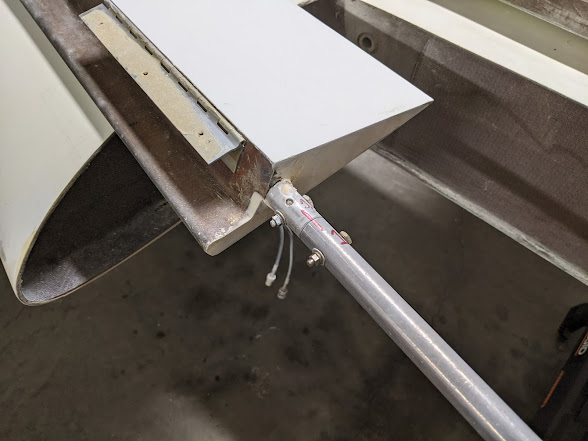
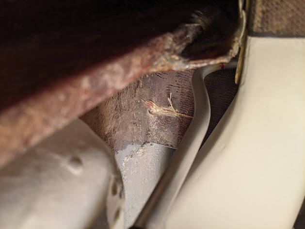
 Started the night by sanding the aileron ends so that they were smooth and to help with fit in cutout. Also connected the torque tube to the aileron.   Once that was done, I moved on to repairing a crack one of the rudders. I noticed this crack when inspecting the rudder a while back. I don't have a picture of it, but the crack was a pretty small ~5 inch hairline along the edge where the glass extends past the foam edge of the rudder (the front rib, basically). I put this off because I thought that I was going to need to repair the underlying glass and wasn't looking forward to it. I used a scraper to break off the micro-balloon where the crack was to see what needed to be done, and was pleasantly surprised to find that there was no underlying damage or de lamination. It seems like something just flexed that edge too far and cracked the micro-balloon layer on the rudder surface. I removed all the loose micro and beveled the edge to transition the secure micro down to the unde...

Wing verification, roll servo hardpoints | 11.27.2020

Image
Now that the garage has enough room for it, we can work on verifying the wing construction. These are fast build wings that were made by the factory, so we don't anticipate any issues, but we'll double check everything and check it off in the book any way. Unfortunately, some of this will need to be one wing at a time. This was just stepping through the plans, one page at a time and verifying everything that I could. I was able to verify everything on the right wing and 99% of the stuff on the left wing that was sitting on the floor as well. It'll need to be up on the sawhorses for the other stuff. I also verified the aileron construction (factory) and the hinge work (Erik), and everything looks awesome. I will need something to remove the years old tape on the hinges, but other than that, no issues. This stuff is real stuck. Aileron attached and checking for free movement. Needs sanded in some spots. Once that was done, I did some glass work. Applied microbubble to the end...

Engine prop governor cover, fuel servo mounting (start) | 11.26.2020

Image
Happy Thanksgiving! Since we did our Thanksgiving meal the day before, we worked on the plane some. So... we made a mistake and installed the mount on the engine prior to installing one tiny little fitting. Unfortunately, that means that we have to unmount the engine from the plane, and unmount the mount from the engine to install the oil pressure transducer fitting. Whoops. Thankfully, while it's off, we can mount the prop governor cover plate which arrived from Van's Aircraft (hey, they were the cheapest cover plate) and the fuel servo right angle adapter, so at least it's not a total waste. The little tiny fitting in the center of this pic is the one that can't be screwed in with the mount on. Once that fitting was in place, I installed the prop governor cover plate. This was ordered from Van's Aircraft, since it's a flat piece of aluminum with some holes in it, and they had the cheapest ones. I guess I can say this plane is basically an RV now, right? After ...

Notch transverse bulkheads for engine mount | 11.24.2020

Image
After talking with Scott from Velocity, he stated that he sees issues with the transverse bulkhead placement occasionally, and that it would be no issue for me to cut recesses for where the nut needs to sit. He said he's even seen planes without the transverse bulkheads at all (*what*) so it won't cause issues. With that, we drilled the holes for the bottom two mount bolts and then I notched out the bulkhead as needed to fit the nut and a smaller washer. Note that the mount will only ever push from the firewall side here, so the large washer isn't needed, unlike the top mount holes, where the weight of the engine is pulling on the firewall when on the ground. Here's where the drill bit punched through on one side. And here's a cleaned up notch for the nut. I started with an undersized drill bit to make an initial circle/hole, and then used a dremel with a flexible extension on it with what amounts to an "end mill" type bit to mill out an even hole and spot...

Autopilot hardpoints, cowl repairs | 11.21.2020

Image
Started off the night by fabricating hardpoints for the autopilot servos out of aluminum. Specifically, I wanted to start installing the roll servo, but figured I'd make all 8 hardpoints while I was making them. Basically just cut squares of aluminum then drill and tap them. Here's the extra four for the pitch servo. Once that was done, I temporarily mounted the GSA28 servo in the bracket and attached the hardpoints. I had to add spacers to the front (nearest the whale tail) to get it to sit in line with the aileron bellcank, because of the curves in the fuselage. The spacers are made from the same stock, but drilled out to bolt diameter. Basically a big flat aluminum washer. Hardpoints installed to the bracket. You can see the spacers I made here too, on the left side. At this point I test fit everything with the bracket in place and drilled the bellcrank for the servo arm. I also ensured that the drilling location allowed for full range of motion with the autopilot overcenter...

Engine mounting | 11.20.2020

Image
We started the engine install by leveling the fuselage front to rear (firewall and canard bulkhead 0 degrees) and side to side (using the spar). Once that was done, we installed the cowlings to be able to determine where the engine should sit on the firewall. These need cleaned up pretty badly. They also need patched from where the Stabells had tried to make them work for their DeltaHawk before deciding to make their own cowlings. Once the measurements were taken, the engine was lifted into place, centered left and right, and set at the correct height. From there, the top hole and two side holes were drilled and bolts placed through. Emily says this picture isn't flattering, but I'm using it anyway. :) PJs are the best plane building clothes. We ran into a few problems with the engine mounting. First, the bolts provided with the kit were too short, so we'll need to order new, longer bolts. Second, the bottom mounting holes line up squarely with the transverse bulkhead. I re...

Engine accessory work, engine mount install, oil cooler lines | 11.15.2020 - 11.18.2020

Image
Started off on the 15th by removing the vacuum pump studs from the engine. I could have left these on and used spacers to take up the space from the cover, but it would have looked janky (in my opinion) and the spacers cost the same as new studs, so I figured I'd just buy new studs when it came time to use this spot again, and install the cover plate with bolts instead. Removing these was a huge pain; they were really stuck in there. I used the typical two jam nuts tightened together, but no matter how tight I made them (really, really tight; like stretched threads tight), all they did was spin off the stud together. I had to attach a vice grip to the studs and spin both at the same time to get them to spin. Good thing I'm tossing these, because the threads were trashed. This hole was then plugged with a Superior 60430 cover plate (why did this cost $40? maybe make your own). I used MS20074-04-06 drilled head (course thread) bolts to install the cover so that I could safety wir...