Wiring harness table, SDS coil pack install | 2.16.2021
Well, it's just about time to start fabricating the wiring harness. There's really not a ton of great info out there about this (avionics in general), so I based this idea off a post on the Van's Air Force forums. For some reason I can't find it now to link it.
Basically, the idea is that you take measurements in the plane, then transfer these measurements to a work surface. The cables are then pulled along the work surface to the end point for that electrical "thing" and held in place. Pull all the cables to everything and you basically have a complete harness.
I modified this idea a bit by mocking up the panel and sub-panel on the table as they sit in the plane. This would eliminate having to measure (and get right!) the majority of the avionics. I can just pull wires to where things sit. (I hope this works out, but have no idea if it will or not. Probably don't use this idea until a later post where it works.)
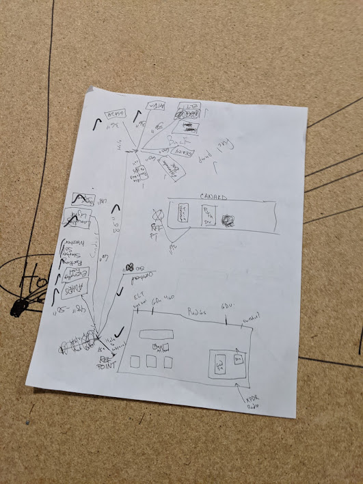
Steve (Emily's dad) and I started by measuring out the lengths for everything not on the panel. We started from a reference point on the co-pilot side of the plane where every wire exiting the panel will drop down to the wiring duct.
 |
| Here's the convoluted map we came up with. |
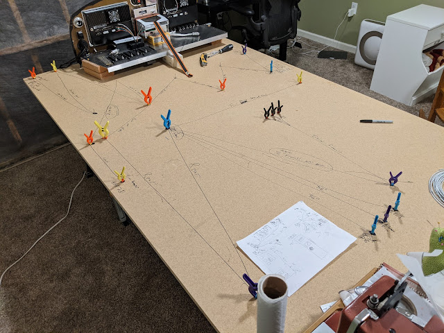
Once that was done, I transferred everything to the table that I had set-up in the guest room/home office/avionics shop. I used nails to mark end-points or to use to wrap around to meet length needs. Note: do not recommend the clamps in this picture. Just use masking tape. Way better.
 |
| Spot the guest bed against the wall to make room for plane stuff. Draw right on the table, it's only $20. :) |
Once that was done, Emily and I installed the SDS coil pack onto the engine, since we received the proper length studs in.
That's all for now!
- Jeff

Comments
Post a Comment