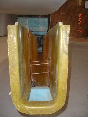
Verification of Previous Build (Part 2) 8.26.2020
Verification log for August 26, 2020.
6. Install wood hard points for control system in keel. This is Erik's photo of the hard point install. They dated the manual 8.15- 8.30 2007 for this part.
7.
8.
9, 10, 11 only applicable for fixed gear kit.
12. Cut out nose gear door hinges. These are fabricated with a template. Ours are currently mounted to the doors, and have obviously been done to spec.
13. Install top Triax pad on firewall for Lycoming engine mount or the lower pads for a Continental engine. Verified they were there but they were slightly undersized for what the manual specifies. Made a note to fix this at a later date.
14. Complete fiberglass portion of nose gear door installation. See picture above.
15.
16. Cut out oil cooler inlet and outlet ducts. Here are some photos from Erik.
 |
| Oil cooler duct |
 |
| NACA scoop on nose for air intake |
 | |||
| Inside of NACA scoop |
17.
18. Install aileron control bracket to keel in rear section. Erik's photo of when he was installing it. We can confirm it is there and permanently installed in the rear of the keel. We spent a long time on the diagram in the book and confirmed proper bolt usage.
19. Install aileron torque tube and control stick in keel. Here's a photo of it in the keel.
20. Mid bearing support installed in keel. Photo above shows that as well.
21. Install main gear and nose gear cylinder. Done but need to check if the cylinder works when we get the pump back from Velocity.
22. Install AN fittings into main and nose gear cylinders and tape over ends. Verified that they are correctly installed.
23. Install flexible hydraulic lines between nose and main gear cylinders. Verified installation is done and the flare is the proper 37 degrees.
24.
25.
26. Structural adhesive front of keel into place. This picture from Erik shows the structural adhesive on the keel.
27. Install keel stiffening layups. Keel is permanently installed in the airplane, and the keel layups were measured and are the correct size and number of layers.
28 is fixed gear only
29. Install nose gear bushing plates. Verified that those were installed correctly.
30. Glass edges of canard cutout to seal it. Canard cut out has been glassed and sanded smooth.
31. Fit and fair in nose access cover. Verified but might need minor sanding.
32. Install nose gear gas spring and shock assembly. Verified that it is there will verify later that it works as intended.
33. Install nose gear door cylinder and assembly. Verified something that will be tested later.
34. Install RG hydraulic power pack. Verified that it is installed, however they had installed a 24 volt and we removed it to be sent off and converted back to 12 volt.
35.
36.
37. Fit instrument panel into airplane. This was done. We will probably install avionics into the existing panel, and then Jeffery will fly the 40 hours of flight testing, test the layout of the avionics, and decide if we want to fabricate a different panel. Current panel has a tilted spot for nav/comm stack.
Skipped down to 44.
44. Install nose gear guides. Photo from Erik of when he did the install.
Called it a night here.


Comments
Post a Comment